An enterprise designer should consider design options in deploying SD-WAN components to account for scalability, high availability, security, and QoS.
Control Plane Design
SD-WAN vManage, vSmart, and vBond can be deployed in one of three cloud-delivered control methods. The design option chosen depends on the company’s IT policies on network infrastructure. A company might want to manage all devices with its internal IT team. Another company might consider the cloud infrastructure services of Cisco or a service provider (SP). Controller deployment models include the following:
- On-premises: An enterprise IT administrator can deploy the vManage, vSmart, and vBond components and manage all configuration of vEdge routers and overlay policy.
- Managed SP: In this model, a service provider deploys the vManage, vSmart, and vBond components in the SP’s cloud infrastructure.
- Cisco cloud deployment: In this model, the vManage, vSmart, and vBond components are deployed in Cisco’s cloud infrastructure.
Scalability
To increase the availability and growth of the orchestration, management, and control planes, it is important to implement horizontal solution scaling. As shown in Figure 11-3, the following can be done to scale a solution:
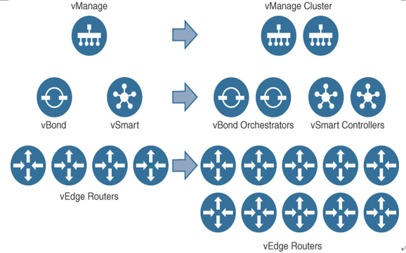
Figure 11-3 Horizontal Solution Scaling
- Add vBond orchestrators to increase vEdge bring-up capacity. Redundancy is achieved by mapping all IP addresses to a single DNS name.
- Create a vManage cluster to support more vEdge routers.
- Add vSmart controllers to increase the capacity of the control plane.
High Availability and Redundancy
Cisco SD-WAN provides many solutions that provide high availability and redundancy. These solutions can be divided into the following categories:
- Site redundancy
- Transport redundancy
- Network/headend redundancy
- Controller redundancy
Site Redundancy
Site redundancy provides redundancy in the event that one of the vEdge routers fails at a site. It can be accomplished by using VRRP from the switched infrastructure or Layer 3 routing from a Layer 3 switch or router. In Figure 11-4, for example, if there is a failure of the vEdge router on the left, VRRP will fail over, and traffic will flow to the vEdge router on the right. If OSPF or BGP is running between the vEdge devices and the router, if the vEdge device on the left fails, the routing protocol will handle the rerouting of traffic to the vEdge router on the right.
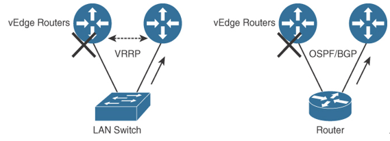
Figure 11-4 Site Redundancy
Transport Redundancy
Transport redundancy allows you to fail over from your primary WAN transport to a secondary transport. For example, in Figure 11-5, if the MPLS circuit fails, traffic will be diverted to the Internet transport.
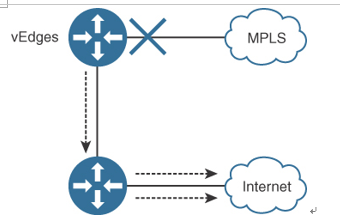
Figure 11-5 Transport Redundancy