SD-WAN provides network/headend redundancy so that in the event of loss of connectivity via the primary network headend vEdge router at the data center, the vEdge router can connect to a redundant headend vEdge router (see Figure 11-6).

Figure 11-6 Network/Headend Redundancy
Controller Redundancy
As mentioned previously, you can increase the number of vSmart controllers to increase the scalability and redundancy of the control plane.
LAN Design
Site LAN designs vary based on size and other requirements. A site can be a simple Layer 2 access switch or a large hierarchical network with multiple distribution and access switches with a Layer 3 core network. Furthermore, SD-WAN can handle separate LAN networks as VPNs (that is, multiple VPNs). Separate VPNs can be implemented to separate regular corporate traffic from, say, PCI traffic and guest wireless. This way, each VPN can be given separate policies. Layer 2 design options include the following:
- Layer 2 with a single vEdge router
- Layer 2 with VRRP for dual vEdge routers
- Layer 2 with a single vEdge router and multiple VPNs
- Layer 2 with VRRP for dual vEdge router and multiple VPNs
Figure 11-7 shows a Layer 2 access switch connected to a single vEdge router, which is a common setup for small branch sites. When additional redundancy is required, dual vEdge routers are implemented, and VRRP is used as the first-hop gateway protocol. VRRP specifies an election protocol that dynamically assigns responsibility for a virtual master router to one of the VRRP routers on a LAN. The virtual router backup assumes the forwarding responsibility for the virtual router if the master fails. VRRP is covered in more detail in Chapter 7, “Advanced Enterprise Campus Design.”
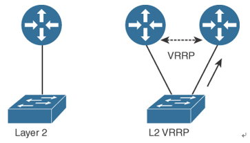
Figure 11-7 Layer 2 Design
Figure 11-8 shows the Layer 2 design but with separate LAN networks (separate IP subnets) that are placed in separate VPNs. When two vEdge routers are used, separate VRRP instances are used to support each VPN.
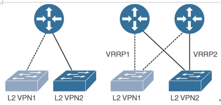
Figure 11-8 Layer 2 Design with Multiple VPNs
Figure 11-9 shows a Layer 3 design where static routes, OSPF, or BGP can be used to exchange routes between the vEdge routers and the Layer 3 switch. At a branch site, a single static route might be enough. Larger sites might use OSPF to exchange routes, and a data center would use BGP.
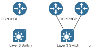
Figure 11-9 Layer 3 LAN Design for SD-WAN
Figure 11-10 shows a Layer 3 LAN design with multiple VPNs. Routes between the VPNs are not exchanged.

Figure 11-10 Layer 3 LAN Design with Multiple VPNs